Howto Phase-shifted Full-Bridge Converter PSFB

When you've put the TL431 right in place, including the correct wiring, then
change your simulation command from .tran 10m 1m to .tran 10m 1m uic
This will show up the simulation graphs after 1msec, which is 10% of the 10msec of the total simulation time.

You can observe the sim.-process on the bottom left.
There are many topics in the simulation settings. Can you tell me exactly which part I should change?
because the simulation didn't work again
 

Anhänge

  • transiet.jpg
    transiet.jpg
    109,9 KB · Aufrufe: 1
When you've put the TL431 right in place, including the correct wiring, then
change your simulation command from .tran 10m 1m to .tran 10m 1m uic
This will show up the simulation graphs after 1msec, which is 10% of the 10msec of the total simulation time.

You can observe the sim.-process on the bottom left.
I want to ask you: Can you set the simulation time and place of TL431 and send the circuit again? I need this very much, please.
 
Have you copied/pasted TL431A.asy and TL431A.lib into the LTspice lib directories ?
If not, do this first, because I have modified the schematic, so you can use TL431A in your circuits without an include command !!

Now, open the files, which I've attached below. It should work !!!!! as you can see from the plots.

Concerning the simulation command, l left the "maximum time step" open. The reason is, if you type in very small values, such as < 100ns (10ns for instance)
the simulation time gets very long and you might think......it's not working.
 

Anhänge

  • Phase_shift_UC3879_GDT_geregelt_Pulslast.asc
    16,3 KB · Aufrufe: 7
  • Phase_shift_UC3879_GDT_geregelt_Pulslast.plt
    1,2 KB · Aufrufe: 6
  • Screenshot (823).png
    Screenshot (823).png
    143 KB · Aufrufe: 7
  • Screenshot (824).png
    Screenshot (824).png
    84,7 KB · Aufrufe: 8
@ umit.
Is it working now ?
Hello, thank you again for your interest and help,
I think the circuits worked this time.
I am sharing the screenshots as well. Is it true ?
 

Anhänge

  • note-uc3875.jpg
    note-uc3875.jpg
    141,5 KB · Aufrufe: 5
  • work - uc3875.jpg
    work - uc3875.jpg
    373,2 KB · Aufrufe: 4
  • note- uc3879.jpg
    note- uc3879.jpg
    144,2 KB · Aufrufe: 6
  • 1- wok ok - uc3879.jpg
    1- wok ok - uc3879.jpg
    407,9 KB · Aufrufe: 3
It looks ok.
The circuit using UC3879 was just my demo circuit.
If you have other parameters for your specifications, you can proceed by using the equations applied in the Converter incl. the UC3875 chip.
Regards
Udo
 
It looks ok.
The circuit using UC3879 was just my demo circuit.
If you have other parameters for your specifications, you can proceed by using the equations applied in the Converter incl. the UC3875 chip.
Regards
Udo
THANKS, can I write to you if I need anything again?
 
Yes, but my service is limited to minor issues. I can't make a complete development free of charge.
 
Yes, but my service is limited to minor issues. I can't make a complete development free of charge.
No problem, can you make improvements for a fee? I can pay the necessary fee.
For example,
Can you add a new soft switching circuit to this circuit and perform power factor correction?
 
Hi Udo,
Can you please let me know how to download theh zip file ?
It gives me an error message

Oops! We ran into some problems.​

 
Dir umit,
did you replace the TL431 (model TL431.mod) by the TL431A. I'm attaching the TL431A lib. Delete the TL431.mod in your circuit and place the TL431A instead.
Error 1 should no longer appear. As mentioend earlier, all files need to be in the same directory. Check if you have all of them.
Furthermore, you can get rid of the message "Pseudoanalysis" if you add uic in the .tran command. Use .tran 10m 1m uic.
Try again my circuit - attached below in the zip file -, which must run automatically. After 1msec of delay, the .plt-file will open, showing up the plots identical to the screenshots., also attached in the zip-file.
Furthermore compare your netlist with the one I've also attached. If there are differences, we will be able to have a closer look to manage the problem.

------
Udo
 

Anhänge

  • Phase shift FB_for umit.zip
    226,3 KB · Aufrufe: 6
@kalanadesilva
Do you still have the question "How to download the zip-file"? Right click on it and store it in your favorable LTspice-directory. Unzip that file to get access to the unzipped files.
-----
Regards
Udo
 
Dir umit,
did you replace the TL431 (model TL431.mod) by the TL431A. I'm attaching the TL431A lib. Delete the TL431.mod in your circuit and place the TL431A instead.
Error 1 should no longer appear. As mentioend earlier, all files need to be in the same directory. Check if you have all of them.
Furthermore, you can get rid of the message "Pseudoanalysis" if you add uic in the .tran command. Use .tran 10m 1m uic.
Try again my circuit - attached below in the zip file -, which must run automatically. After 1msec of delay, the .plt-file will open, showing up the plots identical to the screenshots., also attached in the zip-file.
Furthermore compare your netlist with the one I've also attached. If there are differences, we will be able to have a closer look to manage the problem.

------
Udo
Hello, the file that I was able to run a few days ago is not working now because it is shown as DELETED in TL431 AND UCC3879.

I am sharing the visual of the CIRCUIT . can you help? would you share the working file
 
Die Vollbrücke im Phase-shift Verfahren unterscheidet sich zunächst fast kaum von einer "normalen" Vollbrücke, die ich mal PWM-FB nennen möchte. Doch gibt es einen gravierenden Unterschied, der in der Ansteuerung der Leistungs-MOSFets
liegt. Hier die Unterschiede:
1. PWM-FB
Hierbei werden die MOS meist "über Kreuz", also diagonal im Brückenzweig angesteuert. Die Pulsbreite wird moduliert, d.h. die Einschaltdauer wird - meist bei konstanter Schaltfrequenz - entsprechend der zu regelnden Ausgangsgröße angepasst. Nachteilig ist, daß bei sehr schmalen Pulsen sich Schaltspannung und Schaltstrom überlappen und Schaltverluste produzieren. Um diese im Zaum zu halten, darf die Schaltfrequenz nicht zu hoch gewählt werden.
2. PSFB
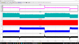
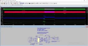
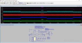
Bei diesem Verfahren werden die Pulsbreiten nicht variiert, d.h. die Einschaltdauer bleibt konstant bei einem Duty cycle von 50%-Totzeit (im nsec-Bereich). Die vertikal angeordneten Fets werden dabei alterierend angesteuert. Die Regelung der PSFB geschieht dadurch, daß die Phasenlage der vertikal angesteuerten Brückenpaare relativ zueinander moduliert bzw. eingestellt werden. Im Vergleich zur PWM-FB kann die Schaltfrequenz höher gewählt werden, das a) die Pulsbreiten konstant bleiben und b) die MOSFet-Kapazitäten durch die ohnehin vorhandene Struinduktivität im Umschwingverfahren umgeladen werden und dadurch die Schaltverluste drastisch reduziert werden können.
Die Wirkungsgrade der Leistungswandler (Konverter) können sich im Bereich von jenseits > 90% bewegen.
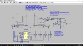
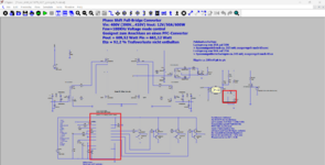
Das angehängte .zip-file zeigt zwei Schaltungen dazu auf, einmal bei statischer Last und einmal bei Pulsbelastung.
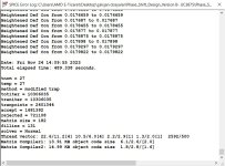
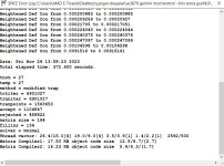
Außerdem wurden zur Stabilisierung des Regelkreises die Transfer-Funktionen unter Zuhilfenahme der LTspice-Laplace Funktion beigelegt und damit auch der Regler (TL431+Optokoppler) dimensioniert.
Der vefrwendete Controller UC3879 ist zwar schon etwas älter, was aber auf das Verfahren keinen Einfluss nimmt. Leider sind von neueren Controller die pspice-models encrypted und nicht vetrwendbar.

mfG, Udo
hello, the file m that I was able to run a few days ago is NOT WORKING BECAUSE TL431 AND UCC3879 APPEAR TO BE DELETED.I am sharing the visual of the CIRCUIT . can you help? would you share the working file
 

Anhänge

  • Adsız.png
    Adsız.png
    136,8 KB · Aufrufe: 2
When you've put the TL431 right in place, including the correct wiring, then
change your simulation command from .tran 10m 1m to .tran 10m 1m uic
This will show up the simulation graphs after 1msec, which is 10% of the 10msec of the total simulation time.

You can observe the sim.-process on the bottom left.
hello, the file m that I was able to run a few days ago is NOT WORKING BECAUSE TL431 AND UCC3879 APPEAR TO BE DELETED.I am sharing the visual of the CIRCUIT . can you help? would you share the working file. Also, I am sharing with you the file that normally works. . Why were these 2 equipment deleted? . How do I add them to my LTSpice program? .If you help me,
 

Anhänge

  • Adsız.png
    Adsız.png
    136,8 KB · Aufrufe: 0
  • Phase shift FB_for umit.zip
    226,3 KB · Aufrufe: 1
Press "Danke" first.
hello, the file m that I was able to run a few days ago is NOT WORKING BECAUSE TL431 AND UCC3879 APPEAR TO BE DELETED.I am sharing the visual of the CIRCUIT . can you help? would you share the working file. Also, I am sharing with you the file that normally works. . Why were these 2 equipment deleted? . How do I add them to my LTSpice program? .If you help me,
 

Anhänge

  • Phase shift FB_for umit.zip
    226,3 KB · Aufrufe: 1
  • Adsız.png
    Adsız.png
    136,8 KB · Aufrufe: 1

Benutzer welche diesen Thread betrachten (Mitglieder: 0, Gäste: 1)

Zurück
Oben