@umit zu post#69
1.Bidirectional PSFB (Bidirectional) + Battery Charge/DischargeUsing the PSFB in both charge and discharge mode Bidirectional PSFB (Bidirectional) + Battery Charge/Discharge
Antwort: Der Phase-Shift Converter, bestehend aus der aktiv angesteuerten Brücke mit den 4 MOS Transistoren auf der Eingangsseite und der Diodenbrücke auf der Ausgangsseite kann nur Energie von der Eingangsseite auf die Ausgangsseite übertragen. Der umgekehrte Energiefluss von der Ausgangsseite zurück zur Eingangsseite ist mit dieser Schaltung nicht möglich.
Um die Energieübertragung nach beiden Seiten, also vom Eingang zum Ausgang und vom Ausgang zum Eingang zu ermöglichen, muss die Diodenbrücke durch aktive Schalter (z.B. MOS-Transistoren) ersetzt werden.
Eine solche Schaltung ist unter dem Namen DAB (Dual Active Bridge) bekannt.
Die Steuerung eines DAB-Konverters im Dual-Modus ist komplex, da sie den Stromfluss in beide Richtungen regeln und die Spannungen an beiden Seiten des Konverters stabilisieren muss. Üblicherweise wird die
Phasenverschiebungsmethode verwendet, um den Leistungsfluss zu steuern. Dabei wird die Phasenverschiebung zwischen den beiden Brücken des Konverters angepasst.
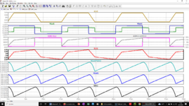
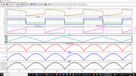
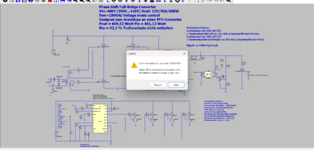
Ich habe dazu 2 Artikel angehängt. Außerdem noch eine LTspice-Simulationsschaltung eines DAB-Converters. Die Anpassung der Signale für den bidirektionalen Energiefluss ist hierbei aber nicht eingearbeitet. Man müsste dafür die Signale für den Buck-Betrieb (vom Ausgang zum Eingang) anpassen. Das ist aber sehr umständlich und nicht sehr praxisgerecht.
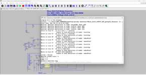
Deshalb wird dafür meistens ein Mikrkontroller eingesetzt. Leider sind solche Komponenten für LTspice nicht verfügbar. Eine Simulation lässt sich deshalb damit nicht realisieren.
2- Multi-Mode PSFB (with ZVS ↔ ZCS transition)Can we make the circuit able to select the most suitable resonance mode according to the load condition?
If the load current is low: switch to ZCS mode. If the load current is high: Stay in ZVS mode.Innovation: Dual-mode resonant switching control algorithm → high efficiency over wide load range.
Siehe Report von Alamri_uncc_0694_13668.pdf.
")