Howto Phase-shifted Full-Bridge Converter PSFB

i probably don't recognize the tl431 and uc 3879 products because I'm using the current version of my system. will you use equivalent products and share the working circuit with me _?the current version I am using right now.version (x64): 24.1.9
 
Hi umit,
the UC3879-file was uploaded by several other users in our group, and no problems occured.

I am attaching the files again. Make sure that all files are in the same directory !!
Where have or did you place(d) your other working files, in which directories? How did you organize your personal working folders. ?
------
Udo
 

Anhänge

  • TL431A.asy
    634 Bytes · Aufrufe: 2
  • Phase_shift_UC3879_GDT_geregelt_Pulslast.plt
    1.000 Bytes · Aufrufe: 2
  • Phase_shift_UC3879_GDT_geregelt_Pulslast.asc
    16,2 KB · Aufrufe: 2
  • UC3879.lib
    5,1 KB · Aufrufe: 2
  • UC3879.asy
    1,5 KB · Aufrufe: 2
  • TL431A.lib
    471 Bytes · Aufrufe: 2
Hi umit,
the UC3879-file was uploaded by several other users in our group, and no problems occured.

I am attaching the files again. Make sure that all files are in the same directory !!
Where have or did you place(d) your other working files, in which directories? How did you organize your personal working folders. ?
------
Udo
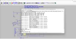
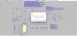
First of all, thank you very much for your return. . I downloaded the files you sent again and saved them all in the same directory. I will try it again from the beginning. It gave me a warning like this, but I said OK and continued, just so you know. and finally he gave a warning.
Hi umit,
the UC3879-file was uploaded by several other users in our group, and no problems occured.

I am attaching the files again. Make sure that all files are in the same directory !!
Where have or did you place(d) your other working files, in which directories? How did you organize your personal working folders. ?
------
Udo
  • First of all, thank you very much for your return. . I downloaded the files you sent again and saved them all in the same directory. I will try it again from the beginning. It gave me a warning like this, but I said OK and continued, just so you know. and finally he gave a warning. But it worked, is there anything you need to update about it?i think there is a problem with the mmbz18val and 2scr293p equipment.Besides, I have a favor to ask of you .

    --I need to add a novelty to my circuit and I have 2 options, can you help me with this?

    1- Bidirectional PSFB (Bidirectional) + Battery Charger/DischargeUsing
    the PSFB in both charger and discharge modeBidirectional PSFB (Bidirectional) + Battery Charger/Discharge


    2- Multi-Mode PSFB (with ZVS ↔ ZCS pass-through)
    Can we make the circuit able to select the most appropriate resonance mode according to the load condition?
    If the load current is low: Switch to ZCS mode.If the load current is high: Stay in ZVS mode.
    Innovation: Dual-mode resonant switching control algorithm → high efficiency over a wide load range.
 

Anhänge

  • Adsız11.png
    Adsız11.png
    149,9 KB · Aufrufe: 2
  • Adsız12.png
    Adsız12.png
    261,4 KB · Aufrufe: 2
First of all, thank you very much for your return. . I downloaded the files you sent again and saved them all in the same directory. I will try it again from the beginning. It gave me a warning like this, but I said OK and continued, just so you know. and finally he gave a warning.

  • First of all, thank you very much for your return. . I downloaded the files you sent again and saved them all in the same directory. I will try it again from the beginning. It gave me a warning like this, but I said OK and continued, just so you know. and finally he gave a warning. But it worked, is there anything you need to update about it?i think there is a problem with the mmbz18val and 2scr293p equipment.Besides, I have a favor to ask of you .

    --I need to add a novelty to my circuit and I have 2 options, can you help me with this?

    1- Bidirectional PSFB (Bidirectional) + Battery Charger/DischargeUsing
    the PSFB in both charger and discharge modeBidirectional PSFB (Bidirectional) + Battery Charger/Discharge


    2- Multi-Mode PSFB (with ZVS ↔ ZCS pass-through)
    Can we make the circuit able to select the most appropriate resonance mode according to the load condition?
    If the load current is low: Switch to ZCS mode.If the load current is high: Stay in ZVS mode.
    Innovation: Dual-mode resonant switching control algorithm → high efficiency over a wide load range.
See Howto - Phase-shifted Full-Bridge Converter PSFB

(Post #17 & #19)
 
Umit, your error message means, you do not have those elements in your library ! If I am right, the missing transistors are in the standard lib of LTspiceXVII.
The best is, you check for LTspice updates. Then you will get more components, filling up your standard library. The standard lib components are in a directory named "cmp".
Another possibility is you search for other transistors which are listed in your library and offer voltage and current requirements for the driver circuit.
--I need to add a novelty to my circuit and I have 2 options, can you help me with this?

1- Bidirectional PSFB (Bidirectional) + Battery Charger/DischargeUsing
the PSFB in both charger and discharge modeBidirectional PSFB (Bidirectional) + Battery Charger/Discharge


2- Multi-Mode PSFB (with ZVS ↔ ZCS pass-through)
Can we make the circuit able to select the most appropriate resonance mode according to the load condition?
If the load current is low: Switch to ZCS mode.If the load current is high: Stay in ZVS mode.
Innovation: Dual-mode resonant switching control algorithm → high efficiency over a wide load range.
 
Es wäre cool, wenn ihr die englischen Fragen auch in "Translater-deutsch" posten könntet, da wir ein deutschsprachiges Forum sind ;)
 
Zuletzt bearbeitet:
Es wäre cool, wenn ihr die englischen Fragen auch in "Translater-deutsch" posten könntet, da wir ein deutschsprachiges Forum sind ;)
YOU ARE RIGHT, I APOLOGIZE. I WAS A LITTLE DISTRACTED. WRITING AND SENDING IN TURKISH WAS A MISTAKE.

--I need to add a new feature to my circuit and I have two options, can you help me with this?:)

1- Bidirectional PSFB (Bidirectional) + Battery Charge/DischargeUsing the PSFB in both charge and discharge mode Bidirectional PSFB (Bidirectional) + Battery Charge/Discharge

2- Multi-Mode PSFB (with ZVS ↔ ZCS transition)Can we make the circuit able to select the most suitable resonance mode according to the load condition?

If the load current is low: switch to ZCS mode. If the load current is high: Stay in ZVS mode.Innovation: Dual-mode resonant switching control algorithm → high efficiency over wide load range.


deutschsprachiges

DU HAST RECHT.ES TUT MIR LEID.ICH WAR ETWAS ABWESEND. ES WAR EIN FEHLER, TÜRKISCH ZU SCHREIBEN UND ZU SCHREIBEN.

  • -- Ich muss eine Neuheit zu meiner Schaltung hinzufügen, und ich habe zwei Möglichkeiten, kannst du mir dabei helfen?

    1-Duplex PSFB (Duplex) + Batterieladung / EntladungVerwendung von Psfb im Lade-und entladungsmodus Duplex PSFB (Duplex) + Batterieladung / Entladung

    2-Multi-Modus PSFB (ZVS mit dem ZCS-Übergang von lloc)Können wir die Schaltung in der Lage machen, den am besten geeigneten resonanzmodus basierend auf dem Lastzustand zu wählen?Wenn der Laststrom niedrig ist: wechseln Sie in den ZCS-Modus. Wenn der Laststrom hoch ist: bleiben sie im ZVS-Modus.Neuheit: Dual-Mode-resonanzschaltungssteueralgorithmus ① hohe effizienz über einen breiten Lastbereich.
 
Umit, your error message means, you do not have those elements in your library ! If I am right, the missing transistors are in the standard lib of LTspiceXVII.
The best is, you check for LTspice updates. Then you will get more components, filling up your standard library. The standard lib components are in a directory named "cmp".
Another possibility is you search for other transistors which are listed in your library and offer voltage and current requirements for the driver circuit.
--I need to add a new feature to my circuit and I have two options, can you help me with this?:)

1- Bidirectional PSFB (Bidirectional) + Battery Charge/DischargeUsing the PSFB in both charge and discharge mode Bidirectional PSFB (Bidirectional) + Battery Charge/Discharge

2- Multi-Mode PSFB (with ZVS ↔ ZCS transition)Can we make the circuit able to select the most suitable resonance mode according to the load condition?

If the load current is low: switch to ZCS mode. If the load current is high: Stay in ZVS mode.Innovation: Dual-mode resonant switching control algorithm → high efficiency over wide load range.
 
Umit, ich werde mir über deine Fragen Gedanken machen.

Vorher würde mich noch interessieren, ob Du die existierende Schaltung des Phase-shift converters simulieren konntest ? Wenn nicht, brauchen wir über Anpassungen noch nicht nachdenken.
 
Umit, ich werde mir über deine Fragen Gedanken machen.

Vorher würde mich noch interessieren, ob Du die existierende Schaltung des Phase-shift converters simulieren konntest ? Wenn nicht, brauchen wir über Anpassungen noch nicht nachdenken.
JA, ICH HABE ES GESCHAFFT, VIELEN DANK . WIR HABEN ES MIT DER LETZTEN SCHALTUNG AUSGEFÜHRT, DIE SIE GESENDET HABEN
 
  • Danke
Reaktionen: Udo
@umit zu post#69

1.Bidirectional PSFB (Bidirectional) + Battery Charge/DischargeUsing the PSFB in both charge and discharge mode Bidirectional PSFB (Bidirectional) + Battery Charge/Discharge
Antwort: Der Phase-Shift Converter, bestehend aus der aktiv angesteuerten Brücke mit den 4 MOS Transistoren auf der Eingangsseite und der Diodenbrücke auf der Ausgangsseite kann nur Energie von der Eingangsseite auf die Ausgangsseite übertragen. Der umgekehrte Energiefluss von der Ausgangsseite zurück zur Eingangsseite ist mit dieser Schaltung nicht möglich.
Um die Energieübertragung nach beiden Seiten, also vom Eingang zum Ausgang und vom Ausgang zum Eingang zu ermöglichen, muss die Diodenbrücke durch aktive Schalter (z.B. MOS-Transistoren) ersetzt werden.
Eine solche Schaltung ist unter dem Namen DAB (Dual Active Bridge) bekannt.
Die Steuerung eines DAB-Konverters im Dual-Modus ist komplex, da sie den Stromfluss in beide Richtungen regeln und die Spannungen an beiden Seiten des Konverters stabilisieren muss. Üblicherweise wird die Phasenverschiebungsmethode verwendet, um den Leistungsfluss zu steuern. Dabei wird die Phasenverschiebung zwischen den beiden Brücken des Konverters angepasst.

Ich habe dazu 2 Artikel angehängt. Außerdem noch eine LTspice-Simulationsschaltung eines DAB-Converters. Die Anpassung der Signale für den bidirektionalen Energiefluss ist hierbei aber nicht eingearbeitet. Man müsste dafür die Signale für den Buck-Betrieb (vom Ausgang zum Eingang) anpassen. Das ist aber sehr umständlich und nicht sehr praxisgerecht. Deshalb wird dafür meistens ein Mikrkontroller eingesetzt. Leider sind solche Komponenten für LTspice nicht verfügbar. Eine Simulation lässt sich deshalb damit nicht realisieren.

2- Multi-Mode PSFB (with ZVS ↔ ZCS transition)Can we make the circuit able to select the most suitable resonance mode according to the load condition?

If the load current is low: switch to ZCS mode. If the load current is high: Stay in ZVS mode.Innovation: Dual-mode resonant switching control algorithm → high efficiency over wide load range.

Siehe Report von Alamri_uncc_0694_13668.pdf.
 

Anhänge

  • Alamri_uncc_0694N_13668.pdf
    2 MB · Aufrufe: 1
  • DAB1.asc
    8,8 KB · Aufrufe: 2
  • Basso_Introduction to the DAB.pdf
    2,6 MB · Aufrufe: 1
  • DAB1.plt
    1.019 Bytes · Aufrufe: 1
Umit, ich werde mir über deine Fragen Gedanken machen.

Vorher würde mich noch interessieren, ob Du die existierende Schaltung des Phase-shift converters simulieren konntest ? Wenn nicht, brauchen wir über Anpassungen noch nicht nachdenken.
I turned on the circuit. Now I'm asking for your help on this matter.

-Multi-Mode PSFB (with ZVS ↔ ZCS transition)Can we make the circuit able to select the most suitable resonance mode according to the load condition?

If the load current is low: switch to ZCS mode. If the load current is high: Stay in ZVS mode.Innovation: Dual-mode resonant switching control algorithm → high efficiency over wide load range.
 
@umit zu post#69

1.Bidirectional PSFB (Bidirectional) + Battery Charge/DischargeUsing the PSFB in both charge and discharge mode Bidirectional PSFB (Bidirectional) + Battery Charge/Discharge
Antwort: Der Phase-Shift Converter, bestehend aus der aktiv angesteuerten Brücke mit den 4 MOS Transistoren auf der Eingangsseite und der Diodenbrücke auf der Ausgangsseite kann nur Energie von der Eingangsseite auf die Ausgangsseite übertragen. Der umgekehrte Energiefluss von der Ausgangsseite zurück zur Eingangsseite ist mit dieser Schaltung nicht möglich.
Um die Energieübertragung nach beiden Seiten, also vom Eingang zum Ausgang und vom Ausgang zum Eingang zu ermöglichen, muss die Diodenbrücke durch aktive Schalter (z.B. MOS-Transistoren) ersetzt werden.
Eine solche Schaltung ist unter dem Namen DAB (Dual Active Bridge) bekannt.
Die Steuerung eines DAB-Konverters im Dual-Modus ist komplex, da sie den Stromfluss in beide Richtungen regeln und die Spannungen an beiden Seiten des Konverters stabilisieren muss. Üblicherweise wird die Phasenverschiebungsmethode verwendet, um den Leistungsfluss zu steuern. Dabei wird die Phasenverschiebung zwischen den beiden Brücken des Konverters angepasst.

Ich habe dazu 2 Artikel angehängt. Außerdem noch eine LTspice-Simulationsschaltung eines DAB-Converters. Die Anpassung der Signale für den bidirektionalen Energiefluss ist hierbei aber nicht eingearbeitet. Man müsste dafür die Signale für den Buck-Betrieb (vom Ausgang zum Eingang) anpassen. Das ist aber sehr umständlich und nicht sehr praxisgerecht. Deshalb wird dafür meistens ein Mikrkontroller eingesetzt. Leider sind solche Komponenten für LTspice nicht verfügbar. Eine Simulation lässt sich deshalb damit nicht realisieren.

2- Multi-Mode PSFB (with ZVS ↔ ZCS transition)Can we make the circuit able to select the most suitable resonance mode according to the load condition?

If the load current is low: switch to ZCS mode. If the load current is high: Stay in ZVS mode.Innovation: Dual-mode resonant switching control algorithm → high efficiency over wide load range.

Siehe Report von Alamri_uncc_0694_13668.pdf.
I'd like to design a PSFB circuit that provides soft switching and selects the appropriate resonance state based on the load. Could you please share a design that works in this situation with me?
 
Dear umit,
My activities are limited to LTspice simulations. I have no more time available for more development services.
Of course I can have an eye on your design stages with some comments from my side, provided this will not require too many time investigations.
------
Udo
 
So, if 70uH resonant inductance is used in the design you sent me, what is the minimum load value that can be provided without ZVS deterioration?
 
@ Umit,

Please recall post #67, in which our Admin suggested to use the German language to communicate between us and other users. Therefore, I’ll go ahead in German.

Ich habe mehrere Files gepostet, solche für Phase shift-converters und DAB converter.

Da Deine Frage sich auf 70uH bezieht, nehme ich Stellung zum DAB Converter, der diese 70uH als Streuinduktivität (Lleakage) enthält. In den angehängten Schaltplänen habe ich Ltot benutzt.

Ich möchte ausdrücklich darauf hinweisen, dass mein mit #72 geposteter DAB Schaltplan lediglich die Struktur eines DAB-Converters darstellen sollte, um aufzuzeigen, wie ein beidseitiger (dualer) Stromfluss realisiert werden kann. Von einem Design kann dazu keine Rede sein.

In den angehängten Schaltplänen habe ich aber Werte ermittelt, die auf folgende Spezifikation bezogen ist:

V1=800V V2=400V Po=10KW; und 1x Po/20 = 500W. Außerdem Ermittlung der maximal möglichen Leistung mit der Induktivität 70uH.

Auf Grund Deiner bisherigen Fragehistorie habe ich große Zweifel ob Du überhaupt an diesem, oder anderen DAB-Converter Projekt arbeitest. Ich habe Dir Basso’s Dokument gepostet, außerdem gibt es genügend Fachliteratur im Internet.

Deshalb stelle ich mir die Frage: Hast Du überhaupt bisher eine Berechnung vorgenommen?

Unser Forum gibt zwar Tipps, stellt aber keinen Ersatz für Entwicklungsarbeiten dar. Dieses solltest Du mal selbst versuchen.

Viel Spaß bei Studieren der angehängten Files.
Du kannst auch einen Test mit 50Watt = Pomax/200 durchführen.
 

Anhänge

  • DAB1_Pomax.asc
    14,1 KB · Aufrufe: 0
  • DAB1_Pomax.plt
    1,7 KB · Aufrufe: 0
  • DAB1_Pomin.asc
    13,8 KB · Aufrufe: 0
  • DAB1_Pomin.plt
    1,8 KB · Aufrufe: 0
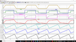
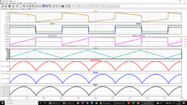
  • Screenshot Pomax.png
    Screenshot Pomax.png
    119,1 KB · Aufrufe: 0
  • Screenshot Pomin.png
    Screenshot Pomin.png
    112,6 KB · Aufrufe: 0
Zuletzt bearbeitet:

Benutzer welche diesen Thread betrachten (Mitglieder: 0, Gäste: 0)

Zurück
Oben